

Views: 176 Author: Jiawei Huang Publish Time: 2025-11-10 Origin: Site


In industrial robots, including welding robots, a coordinate axis usually corresponds to one degree of freedom (DOF) — that is, one independent movement that can be either rotational (revolute joint) or linear (prismatic joint). By combining multiple axes, a robot can position its end effector (the welding torch) anywhere in space and orient it as needed.
The motion of the robot is typically described in several coordinate systems:
• Joint Coordinate System: Each axis or joint has its own rotational or translational position value.
• Cartesian (World) Coordinate System: Describes the end-effector position along X, Y, and Z directions, relative to the robot’s base or workspace origin.
• Tool Coordinate System (TCP): Defined relative to the welding torch, describing the torch tip’s position and orientation in space.
• User or Workpiece Coordinate System: Defined based on a specific workpiece or fixture, making programming and positioning easier.
Each axis can be viewed as a controlled joint or an additional motion unit (such as a turntable, linear rail, or positioner).
In most welding robots, a 6-axis configuration (6 DOF) is standard, often extended with additional external axes (e.g., torch rotation, positioner, or track) to form 7-, 8-, or even higher-DOF systems.
For example, some advanced systems integrate a six-axis robot with two positioners, creating an eight-axis linked welding platform for complex structures (Metals, MDPI, 2025).
In robot motion planning, selecting the appropriate axis configuration, determining the motion sequence, avoiding singularities, and ensuring smooth torch trajectories are all critical to achieving high weld quality, efficient motion, and collision-free operation.
The following introduces a typical six-axis welding robot configuration, along with optional external axes used in large-structure welding.

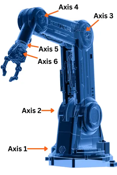
Axis 1: Base Rotation
• Location: At the robot’s base, rotating around a vertical axis.
• Function: Rotates the entire arm to cover a wide working range and point the welding torch toward the starting position.
• Application: Large workpieces such as vehicle frames, railcar bodies, and ship panels, where the robot must rotate around the base to reach extended weld seams.
Axis 2: Shoulder Pitch
• Function: Connects the base to the upper arm, allowing the arm to swing up and down.
• Application: Adjusts the vertical position of the welding torch to handle welds at different heights.
Axis 3: Elbow Pitch
• Function: Controls the extension or retraction of the forearm, affecting the distance between the base and the torch.
• Application: Enables the torch to reach deep or distant weld zones inside large assemblies.
Axis 4: Wrist Pitch / Roll
• Function: Located near the end of the forearm; adjusts the torch’s tilt and orientation.
• Application: Essential for welding inclined, curved, or non-horizontal seams.
Axis 5: Wrist Yaw
• Function: Rotates the welding torch around its central axis, changing the torch pointing direction.
• Application: Useful for circular, corner, or angled welds requiring continuous torch rotation.
Axis 6: Wrist Roll (Torch Rotation)
• Function: Provides fine rotational control at the end effector, allowing smooth changes in torch attitude.
• Application: Maintains consistent welding posture along complex paths such as curved or spiral seams.
External Axes / Tracks / Positioners
For large workpieces (ship structures, railcar bodies, agricultural machinery):
• Linear Tracks: Move the robot along a straight path to expand its workspace.
• Positioners (Turntables or Tilt-Rotators): Rotate or flip the workpiece, reducing the robot’s required arm reach and improving welding accessibility.
• Multi-axis Collaboration: Combined systems such as “six-axis robot + dual positioner” enable coordinated motion for complex geometries (Metals, MDPI, 2025).
These external axes are also considered part of the robot’s coordinate system, even though they are not built into the robot arm itself.
In our welding applications, we commonly use the Tool Coordinate System (TCP).
This system defines the position and orientation of the welding torch tip (Tool Center Point) as the reference for all movements.
It allows the robot to move relative to the torch itself, rather than its base or joints.
Advantages:
• Easy to program: Movements can be directly defined along the torch directions (X, Y, Z), making path teaching more intuitive.
• Stable welding quality: The torch maintains a constant angle and distance from the weld seam.
• Flexible and universal: Once the TCP is set, it can be applied to different workpieces or fixtures without recalibration.
This coordinate system is widely used in industrial welding robots because it ensures both accuracy and convenience in programming.


